
 English


The method of geometric dimensioning and tolerancing (GD&T) makes it possible to communicate technical design requirements precisely. The use of datums—points for measuring dimensions and tolerance specifications—is a crucial component of GD&T. This essay will analyze the idea of datums in GD&T, discuss their significance, and look at the several kinds that are crucial to guaranteeing reliable and reliable output.
Datums in GD&T consist of descriptive components used to establish the coordinate system and maintain geometric relationships between objects. These references serve as a basis for measurement and analysis and help to align and orient components during development and assembly.
Primary datums are the first references specified in the GD&T control framework. They provide a preliminary basis for establishing a cohesive plan for a segment. The selection of primary datums is usually based on the functional requirements of the system and is critical to ensuring proper compatibility and integration of rapid maufacturing components.
Secondary datums are additional contextual information used to refine the coordinate system established by the primary datums further. They play an important role in maintaining additional degrees of freedom and ensuring the geometric integrity of the whole part. The selection of the secondary datums depends on the specific tolerances and considerations required in the plan.
Third-level datums are the third reference feature in the GD&T system. They are used when greater accuracy is required, usually for complex designs where tight tolerances must be maintained. Third-level datums help check fine details and deviations in the geometry of the part.
Datums are reference points, lines, or planes used to control part geometry in GD&T. They are classified as primary, secondary, or tertiary, each serving a distinct role in ensuring accuracy and functional integrity.
| Datum Type | Purpose | Key Role | Example Use |
|---|---|---|---|
| Primary Datum | First reference feature | Establishes the foundational plane or axis for measurement | Base surface of a bracket, main hole for assembly |
| Secondary Datum | Refines coordinate system | Constrains additional degrees of freedom, ensuring correct orientation | Side surface or edge for alignment relative to primary |
| Tertiary (Third-Level) Datum | Final reference feature | Provides full 3D constraint and checks tight tolerances | Small locating features, precision holes, or slots |
Summary:
Primary datum → main reference for orientation
Secondary datum → refines orientation, controls more degrees of freedom
Tertiary datum → final reference, ensures complete 3D accuracy

Datums provide an accurate and standardized location for measurement at various stages of construction. This ensures that the final product conforms to specified design requirements.
The use of datums facilitates alignment and assembly during low volume manufacturing and production. This is critical to ensuring efficiency and effectiveness in the finished product.
Datums play an essential role in managing dimensional tolerances. By identifying points, GD&T allows engineers to communicate acceptable variations in size, style, and orientation within defined limits.
In quality control and inspection, datums simplify the process by providing a consistent basis for checking the conformity of the manufactured part to design specifications.
Datum Feature Simulators are indispensable tools in the Geometric Dimensioning Tolerance (GD&T) inspection process, providing a visual and practical way to verify measurement accuracy. These simulators go beyond reproducing datum features. Just They actively contribute to the overall quality assurance process.
Datam feature simulators not only simulate datum proximity but also help verify the functional relationships of various features on a part. This is especially important in complex systems where many interacting factors greatly influence the overall performance of the product. By using simulators to simulate these interactions, monitors can ensure that the intended working relationships are maintained.
The connections of datum features at different assemblies are sharp and critical for proper fit and alignment. Datum Feature Simulators, when designed to simulate assembly conditions, provide a realistic representation of how parts interact in the assembly process. This dynamic simulation ensures that designed parts do not meet individual tolerances, only loose alignment in the final product.
Some systems may require specific consideration of tolerance zones, especially in areas where multiple factors come together. Datum-feature simulators can be constructed to test and verify measurements within these tight tolerance zones, allowing for a thorough analysis of the compliance of the part with design requirements.

The datum feature simulator is an interactive learning tool used to train operators involved in the survey process. The inclusion of these simulators in training programs provides individuals with hands-on experience, increasing their understanding of how datum features affect measurement. This practical approach offers skill development and proficiency in GD&T applications.
Datum feature simulators provide a platform for creating problem-solving scenarios. Analysts can use these simulators to address potential problems that may arise when analyzing a fundamental part. This approach enables the development of practical solutions and strategies to solve challenges in real-world manufacturing.
Datum reference frames represented by letters (A, B, C, etc.) form the backbone of Geometric Dimensioning Tolerance (GD&T) systems, providing more than method identification through detailed analysis of design concepts, manufacturing efficiencies, and their success in the realization of precise functional products impact is highlighted.
Datum reference frames play an essential role in communicating design ideas but also affect the feasibility of products. Engineers must balance providing a clear and accurate datum reference frame with design requirements and ensuring that the construction team can achieve the specified tolerances and alignments.
The datum reference frame allows flexibility during design iteration. As engineers adjust and modify the system, they can adapt the datum system to change without having an overall understanding of the part coordinate system. This variation contributes to the repetitiveness of the design process, producing continuous improvement.
In the age of digital technology, datum reference frames have been easily integrated into digital design tools and simulations. Digital representations of the datum hierarchy enable design communication and collaboration and allow real-time adjustments and visualization of the effects of tolerances and alignments.
Datum reference frames play an important role in automated inspection systems. Using digital representations, software systems can run inspection processes, reducing manual effort and reducing the risk of human error. This integration enhances the efficiency of all quality control procedures in today's manufacturing facilities.
GD&T datums serve as essential references for programming, setup, and inspection in CNC Machining. Using correctly of datums ensures that every feature of a part is manufactured and measured under right path, meeting functional and assembly requirements.
Datums provide a coordinate system for the CNC machine. The machine interprets the part’s geometry relative to primary, secondary, and tertiary datums.
By referencing these points, surfaces, or axes, programmers can define tool paths accurately, ensuring holes, slots, and complex geometries are correctly located.
For example, a primary datum plane on a base surface can serve as the origin for all X, Y, Z coordinates in the CNC program.
Datums help position and fixture the workpiece on the CNC machine during CNC machining.
Primary datums are typically clamped first to establish the main orientation, followed by secondary and tertiary datums to constrain remaining degrees of freedom.
This ensures the part is stable, repeatable, and aligned for all machining operations.
After machining, features are measured relative to the datums to verify tolerances and alignment.
Using the same datum references in both programming and inspection ensures consistent results and minimizes errors caused by misalignment.
This is especially critical for tight-tolerance or complex parts where even small deviations can affect assembly or performance.
Accurate positioning and orientation of parts
Reduced setup errors and rework
Consistent feature location and tight tolerance control
Streamlined inspection and quality verification
Better integration in assemblies and functional performance
Datum reference frames, when standardized and observed internationally, contribute to global understanding and harmonization. Engineers and manufacturers across industries can easily interpret and apply mold design specifications, enhancing a consistent approach to GD&T and reducing the chances that errors will occur due to local changes in characters.
Datum reference frames are an essential part of digital data exchange between design and construction teams. Standardized digital stations facilitate the seamless transfer of information, ensuring that the standard datum system is communicated and understood, regardless of geographic location.
Datums in GD&T are crucial to achieving precision, accuracy, and quality in manufacturing. Together, primary, secondary, and tertiary data form a reliable reference framework that guides product development and research design. By understanding the importance of data and its quality, engineers can increase the accuracy and reliability of their designs, thereby improving productivity. Remember to consider datum feature simulators and reference frames as additional tools to ensure seamless implementation of GD&T.
Thank you for visiting TEAM MFG. We’re here to help you turn your design into reality — from rapid prototyping to full‑scale production. TEAM MFG applies good tolearnce in our rapid prototyping services, CNC machining services, injection molding services and die casting.
Phone (Asia): +86‑156 2531 2373
Email: ericchen19872017@gmail.com
Address: 1st Floor, Building A, 8th Kuixing Road, Xiaolan Town, Zhongshan City, Guangdong, China
If you’re located in the USA or Europe and need assistance — whether you’re sourcing prototypes, low‑volume runs, or mass production — our team is ready to support you with:
DFM (Design for Manufacturing) feedback tailored to your region’s standards
Quoting in USD/EUR, volume and tooling cost breakdowns
Logistics/lead‑time support for overseas shipping
Quality assurance aligned with international regulations
Please upload your CAD files (STEP, IGES, STL, etc.) and share as much information as you can: dimensions, material, surface finish, quantity, target shipment region, and any special requirements. The more we know, the faster and more accurate our quote.
With over a decade of experience and customers across 70+ countries, we specialise in bridging global design intent with Chinese manufacturing efficiency — delivering precision, speed, and cost‑effective solutions.
A datum in GD&T is a theoretical reference point, line, or plane that serves as the foundation for defining the location and orientation of other features on a part. Using datums ensures consistent measurements, accurate manufacturing, and proper assembly, reducing errors and rework.
A datum feature is a real, physical feature on the part, such as a surface, hole, or slot, that is used to establish a reference. The datum is the exact, theoretical reference derived from that feature. This distinction helps ensure precise measurement and machining alignment.
Datum plane: A flat surface used as a primary reference.
Datum axis/line: A centerline derived from a cylindrical or rotational feature.
Datum point: A specific point used for locating features.
Choosing the right type of datum ensures correct tolerance control and measurement in prod
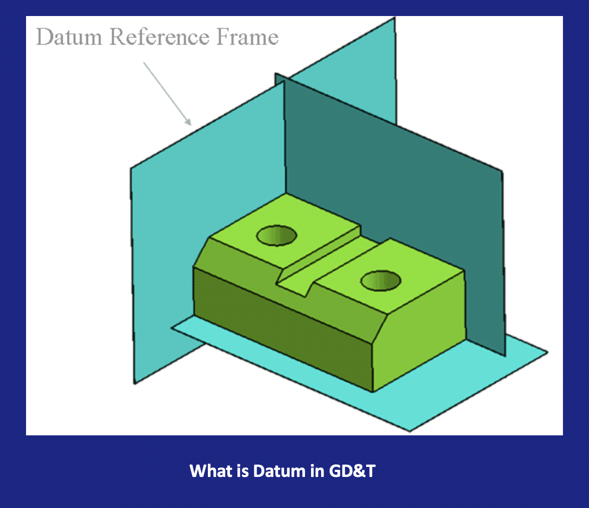
A Datum Reference Frame is created by combining primary, secondary, and tertiary datums to fully constrain a part in 3D space. This framework guides inspection and machining, ensuring all features are referenced consistently for accurate manufacturing and assembly.


